As the motor testing has shown, some motors benefit from the quality of the drive. Here is the development of a state of the art ‘Pure Analog Drive’ motor supply. Scroll down for the new Voyd upgrade PSU.
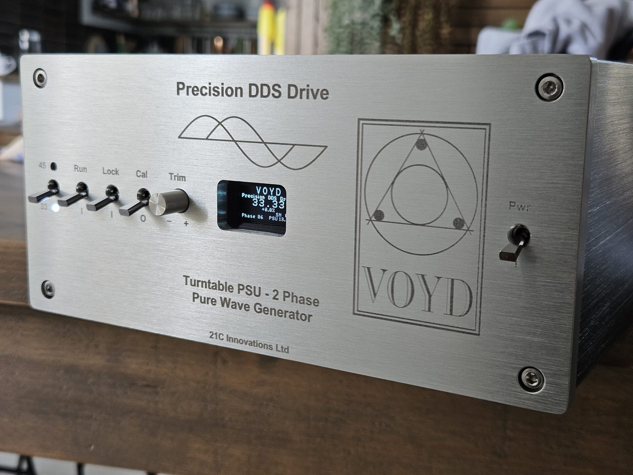
The goal was to develop a pure analog, 3 phase, ultra-low distortion motor drive (primarily for the XXXX motor). Yes there is a digital element to monitor the status but this can be switched off (micro-controller held in reset, display and uC clock off) so in this mode the supply is pure analog – there are zero digital elements switching which makes sense for a turntable which is an analog device…. The drive is as stable as the best digital ‘synthesised’ units but is pure analog…..
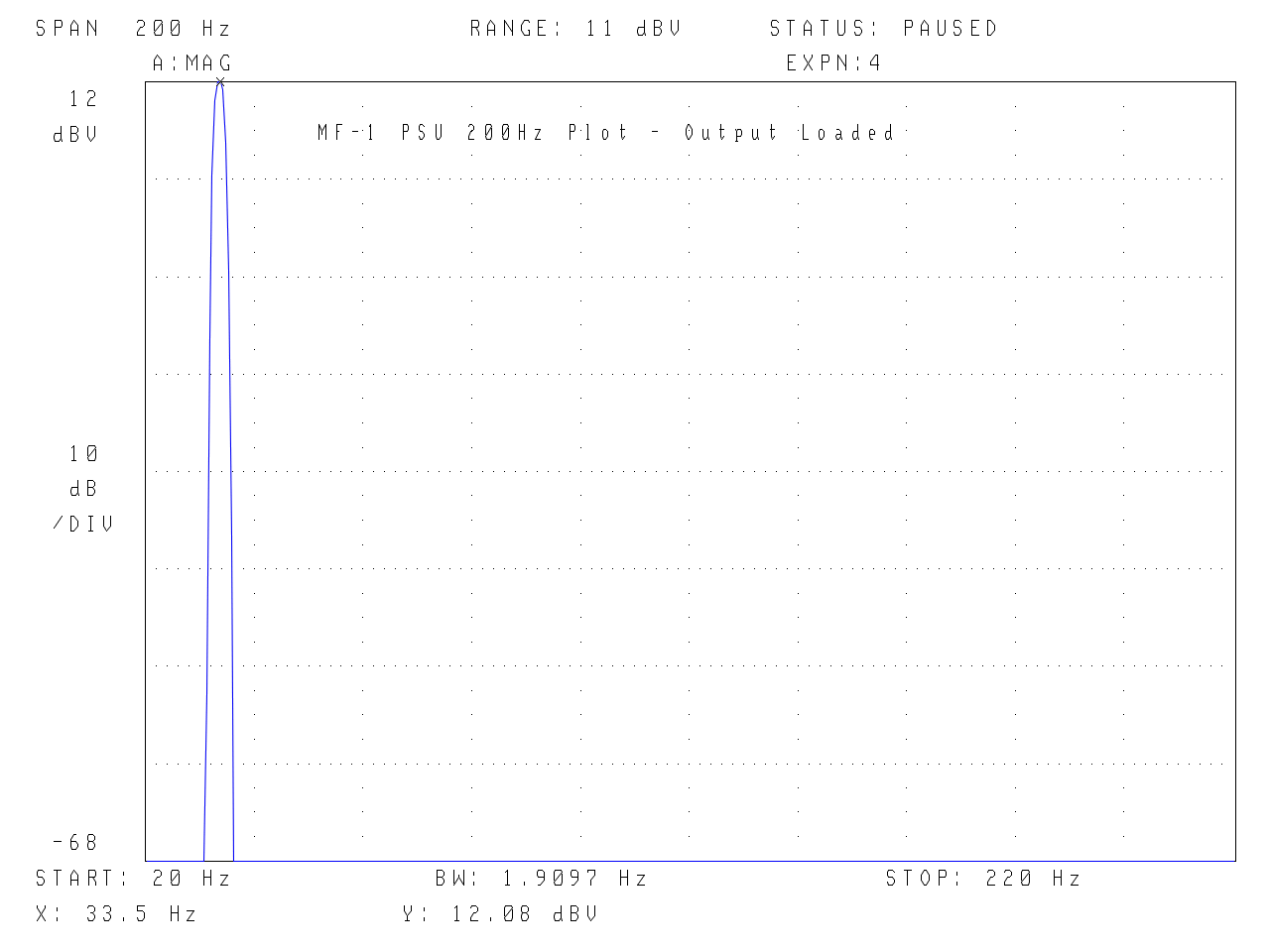
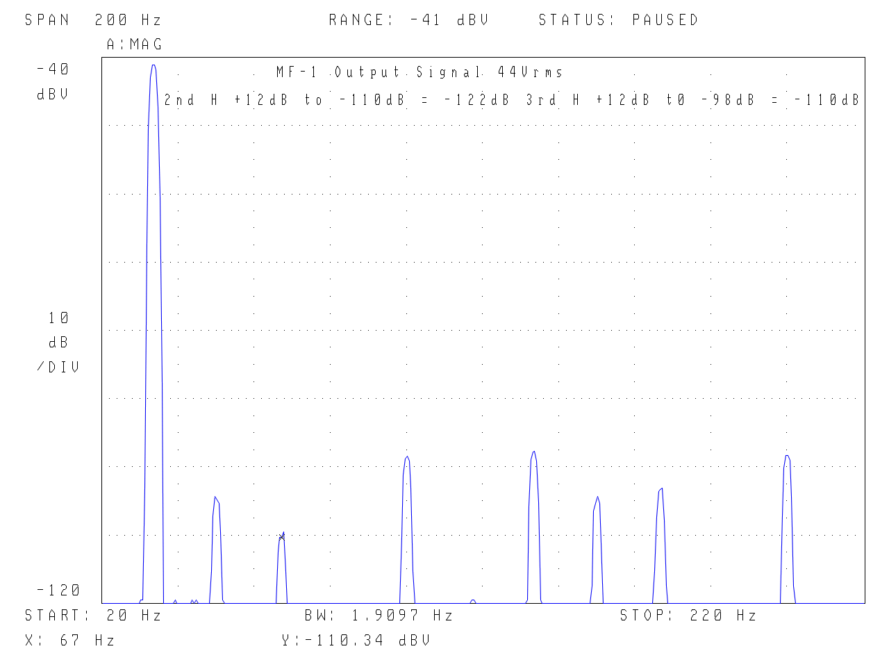
The performance is darn good; 2nd, 3rd etc. harmonic distortion of the generator is -116dB. This can also be described as less than 1.5 parts per million distortion or 0.00015% or 66uV. The output distortion at full voltage (44V RMS, 124V pk-pk), including the 3 phase amplifiers is -110dB (3ppm/0.0003%) and the phase accuracy is better than 0.1 degrees for the 120 and 240 degree signals. Under real motor load it achieves -107dB (4ppm/0.0004%) which took some work utilising the effective constant current of 3 phases and the drive amplifiers power supply rejection ratio (PSRR) which has a measurable influence at these ultra low distortion levels. Also any 50Hz mains component is -112dB. The frequency/speed tracks within 0.01rpm with no impact on the high Q and thus distortion of the R-C oscillator. The diagnostics have been very carefully implemented so as to i) have no influence on the pure analog signal generation and ii) be accurate. (For context the Voyd power supplies have 2nd harmonic distortion of -45dB, 5600 parts per million or 0.56% – I wish I had had this equipment back then, 40 years ago…)
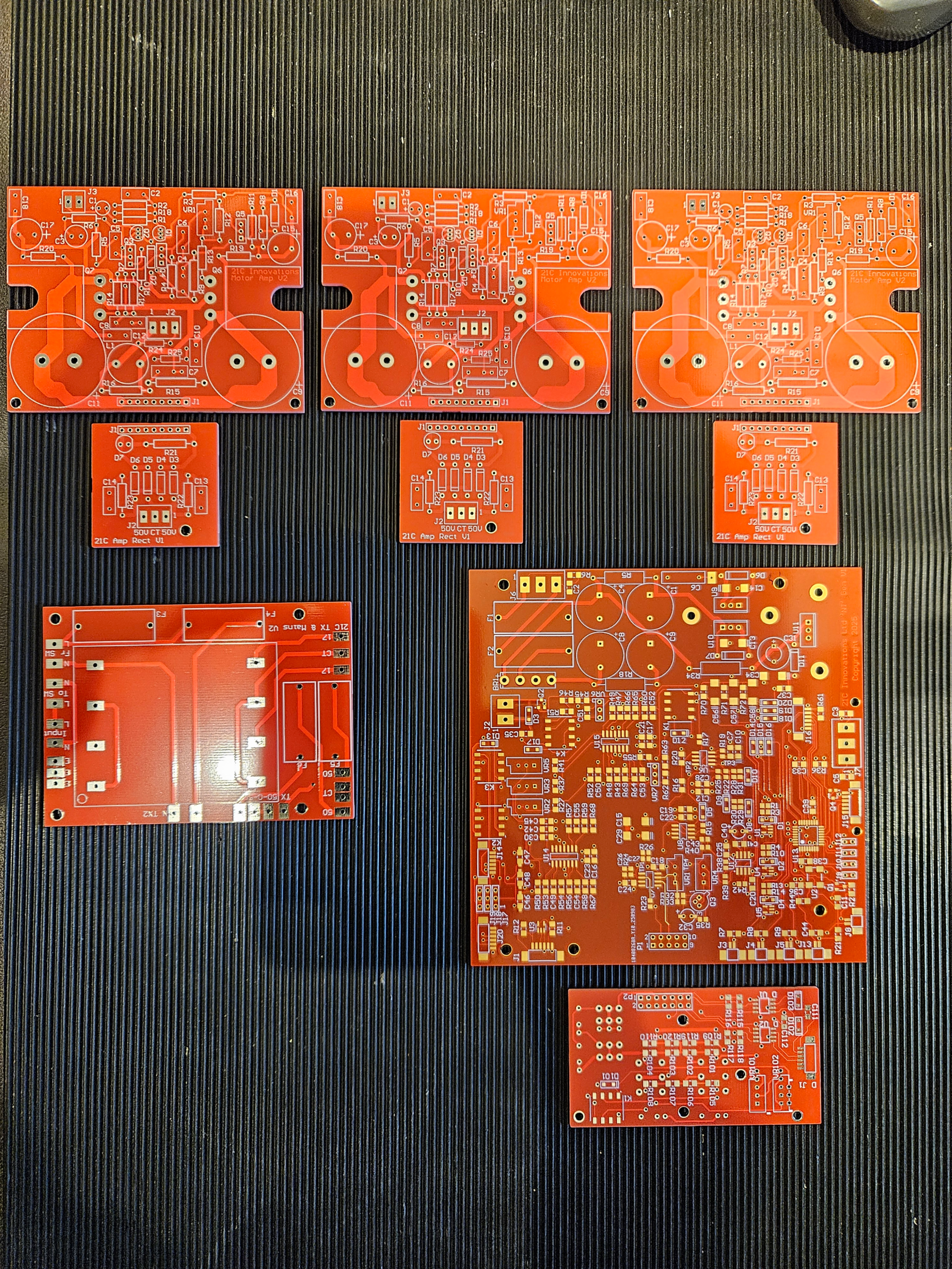
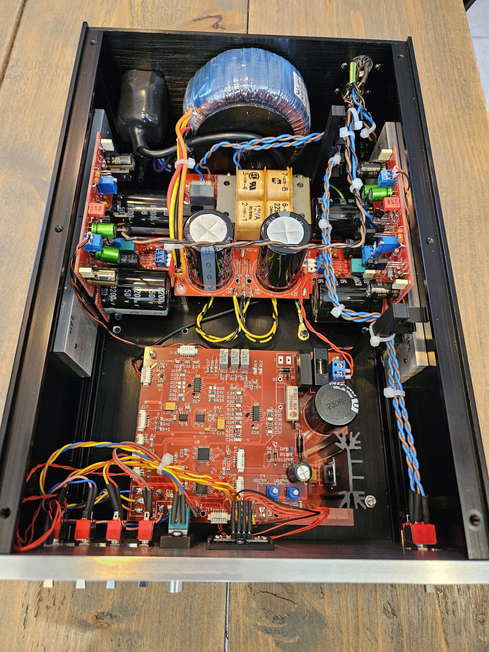
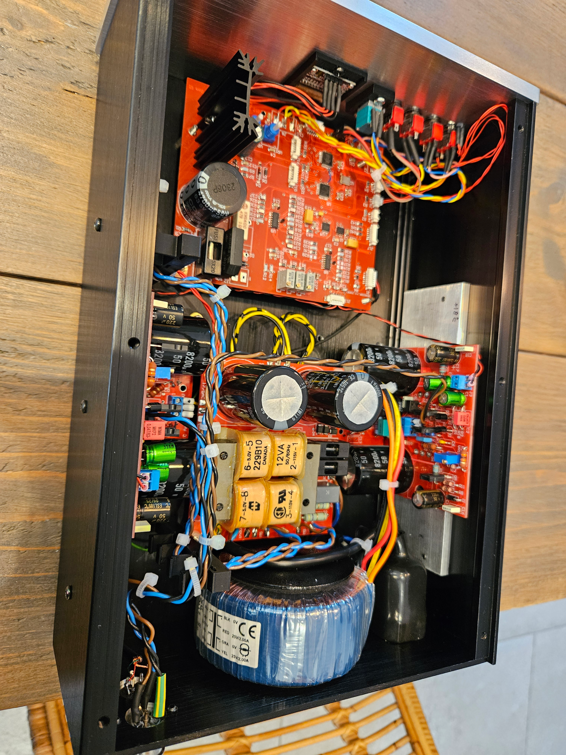
The main generator board is 6 layers with dedicated planes for +15, -15, +5, 0V and two signal routing layers. The critical R-C elements are on a plug in (gold contacts) board. The unit can be configured to generate any frequencies from 25 – 200Hz. In order to achieve this level of performance a significant amount of development work went into this no holds barred design.
This is a key development, as the results attest, and allows turntable development without any concerns there is a better power supply… Oh, the ‘MF-1’ stands for Motor First 😉 – It appears the majority of turntable design is based on mechanical first approaches, whereas I firmly believe turntables should be developed from a motor first principle, hence the MF.
.
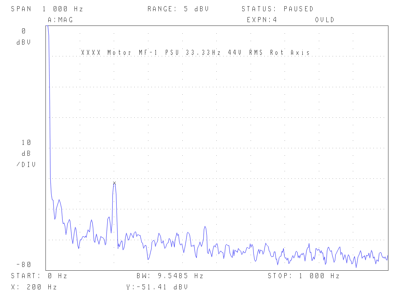
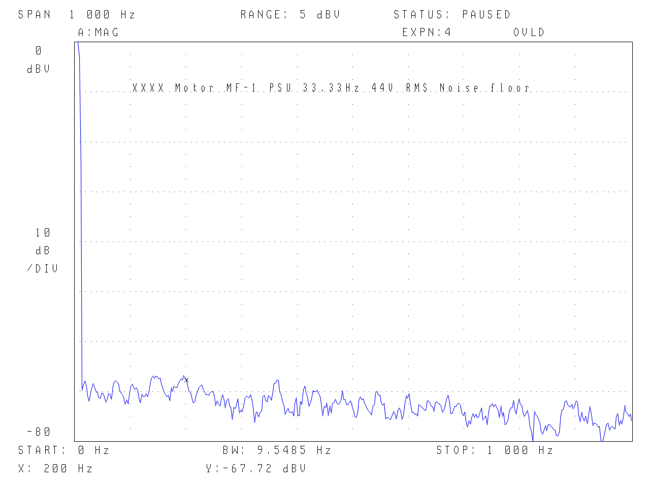
Spectrum – limited to -80dB by HP3561A Signal Analyser 33.33Hz – yes 33.33Hz (& 45.00Hz) running the XXXX motor at 1000rpm (1 Joule of energy!). 1350rpm for 45.
.
Spectrum of Total PSU using an active notch filter to increase the dynamic range of the signal analyser. Note the signal level (after a divider to pad down the 44V rms to a safe level) is +12dB. The small content at 50Hz is likely due to the case of the active notch filter being aluminium and not providing any magnetic screening.
.
Here are the accelerometer plots….. The peak at 200Hz is the 3 phase cycles at twice the drive frequency (AC drives on both the positive and negative peaks) – essentially the drive frequency. The peaks that used to exist at lower frequencies are much reduced and can now be seen dropping to a null during the precise adjustment of phase and voltage. Also running true 3 phase drive allows lower voltages to be used and still achieve significant torque.
.
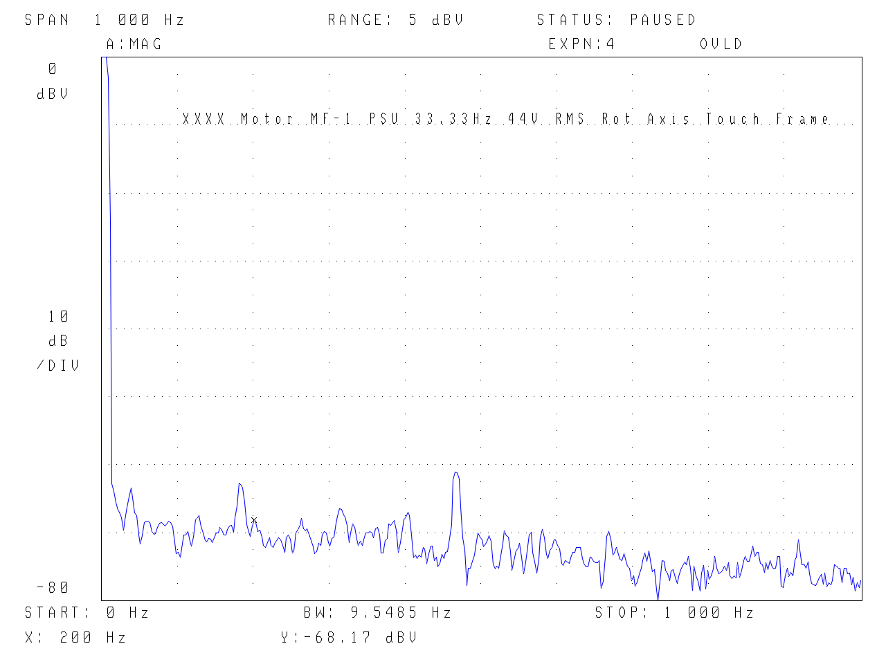
As we know – vibration in these plots is primarily due to speed variation along with a small contribution from the electro-mechanical energisation of the coils/winding which is 200Hz. Touching to the frame shows how small this energy level is. A new speed counter is needed as the noise floor of the current 16bit one is maxed out…
.
And the noise floor….
.
New – Voyd Upgrade:
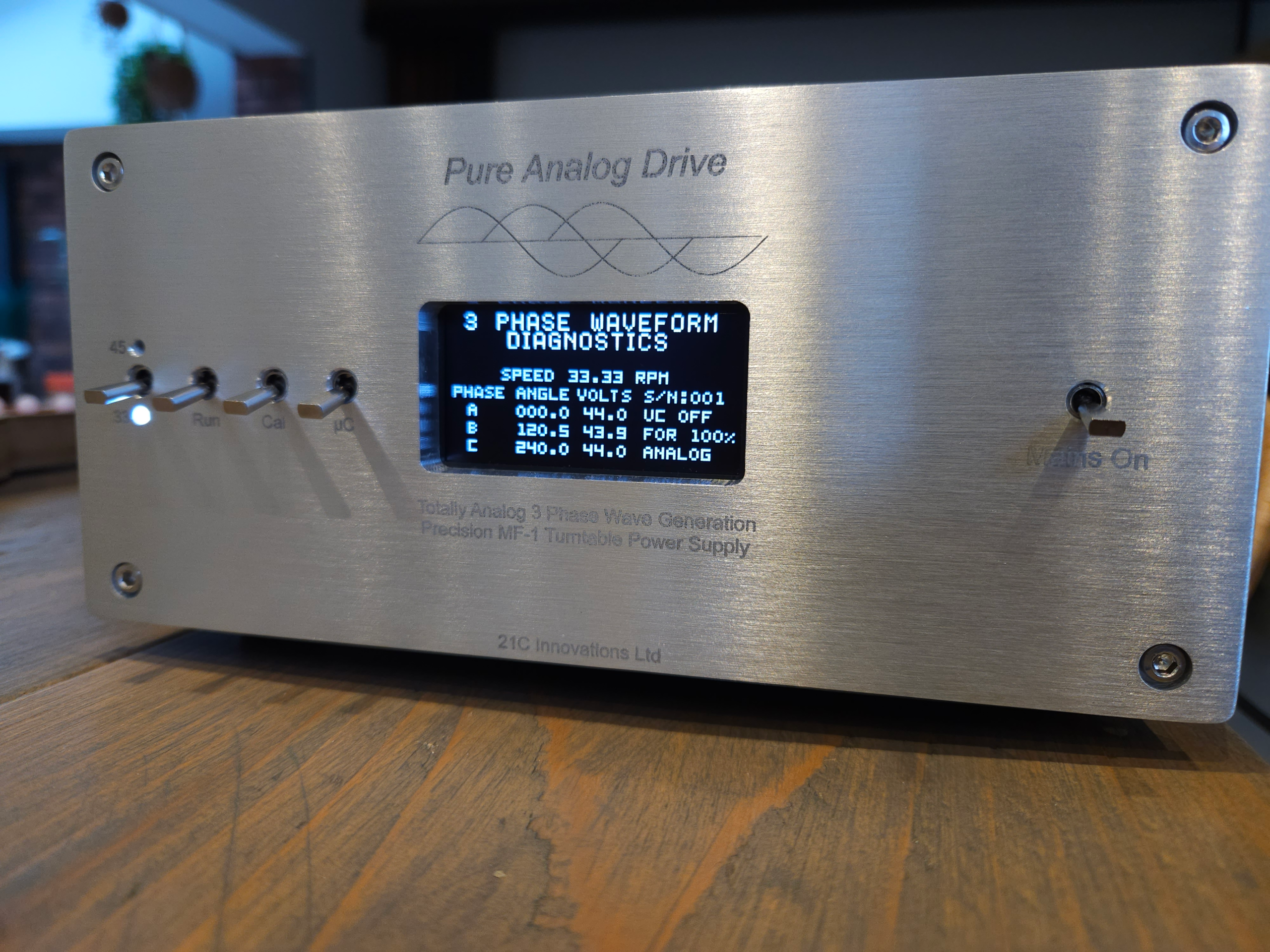
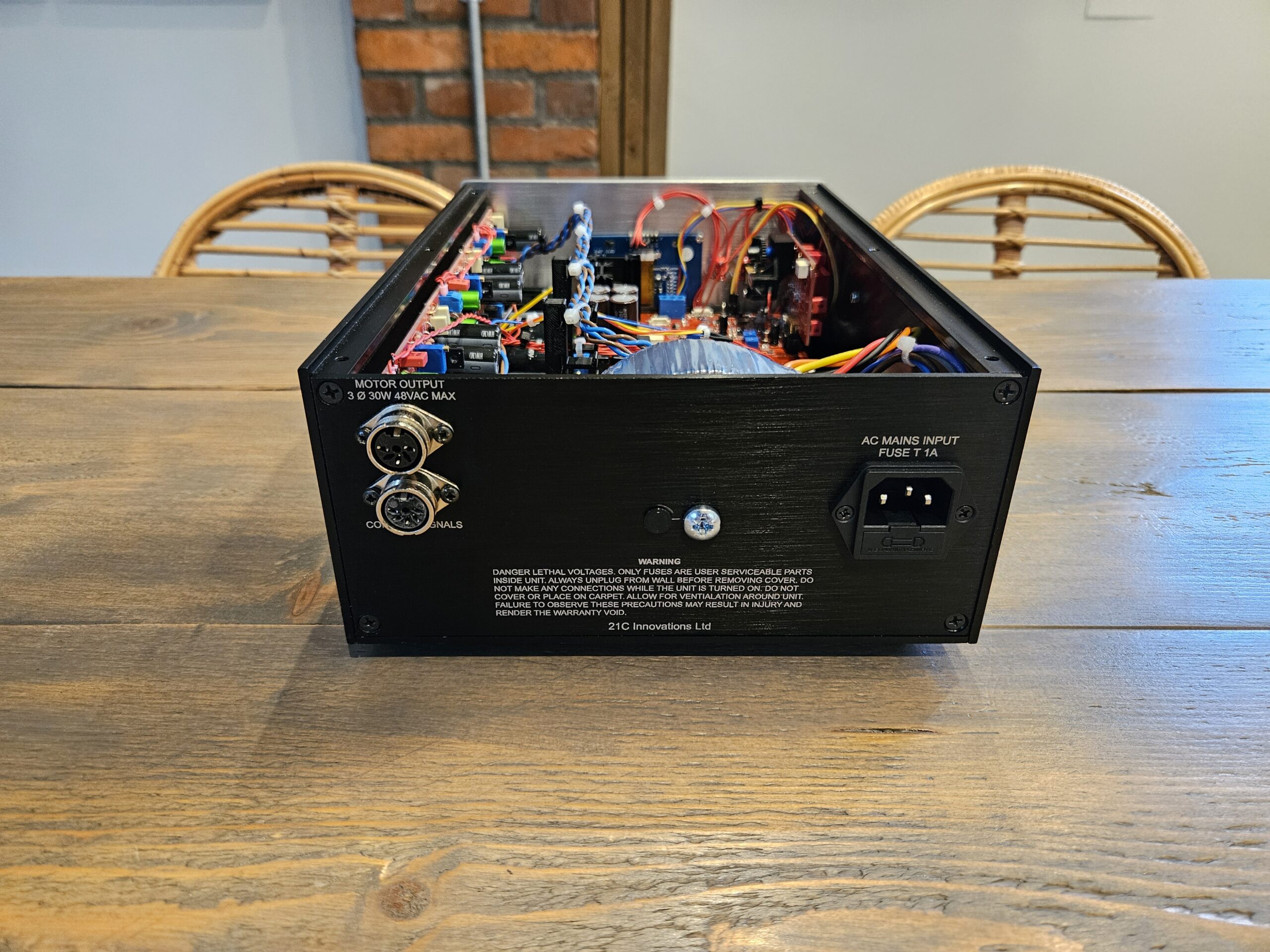
The goal was to disappear into the Lab and develop an electronic drive to get the most out of the B112 Voyd/Valdi Motors. A different approach was taken – initially to see if it was possible to get close to the pure analog generation approach above. Using two microcontrollers – one for housekeeping, the other for waveform generation and a true 16 bit multi-channel DAC it has been possible to get some very respectable results – the waveform generation is clean in the region of -106dB and the whole power supply under full load of 3 motors is – 91dB (0.003%). More on this later but in summary two phase motors as opposed to three phase does introduce more complex demands on the power rails as it pushes on the second harmonic distortion element as well as the AC 50Hz supply lining up with the 2nd harmonic of 25Hz. Given the performance of the 40 year old power supplies, we are looking at several orders of magnitude improvement in the specification and now is well into the law of diminishing returns… Importantly, as well as the electro-mechanical performance, phase adjustment, ultra stable timing, there are some new features – speed trim (+0.9/-1.9% in 0.1% increments) and a turntable calibration mode – the platter speed is measured over 10 revolutions using a sensor and this is then used to correct the speed to exactly 33.3rpm…… Lots of other thinking, dual supplies, schottky rectifier etc.
As we know, the Voyd, Valdi etc, are more immune to motor speed variation due to the balance of the drive geometry, however because of the combined torque and light platter, speed variation must still be minimised to ensure a truly constant platter speed under all conditions. What does it sound like? More detailed low frequencies, better dynamics across the board – like a veil has been lifted. ( even with a humble Valdi with 25mm Voyd platter, RB250, 1020). Other opinions to follow…
.
.
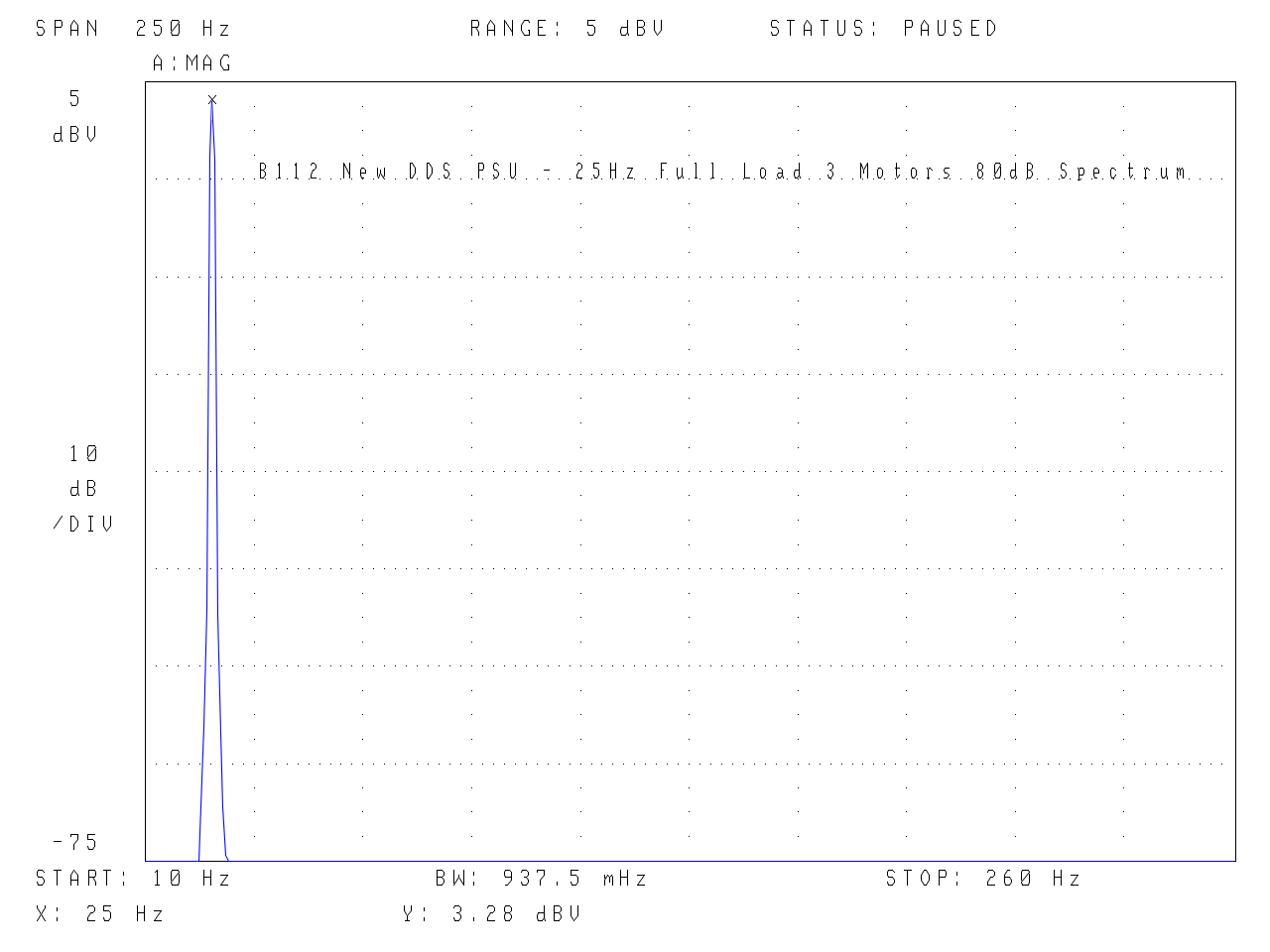
First is the purity of the power supply – limited by the 80dB dynamic range of the analyser. Clean as a whistle under full load (yes, I used a Hanning window for this – normally I don’t as the flat top has a faster acquisition)!
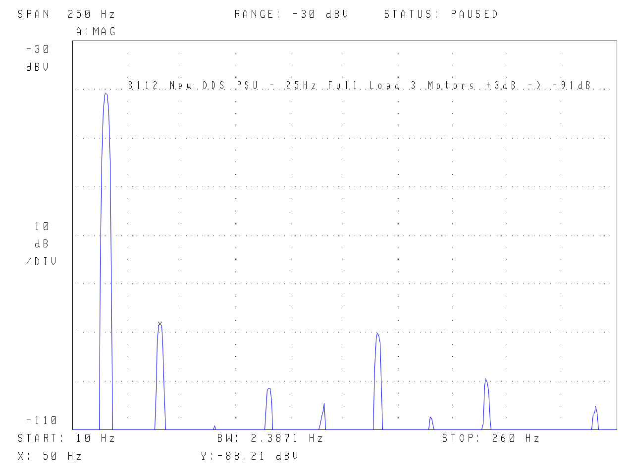
Below – using a very narrow active notch filter to extend the dynamic range…. remember the first large peak is the 25Hz fundamental that has been reduced to allow the very low harmonics to appear. The second smaller peak with the tiny cursor (x) on the top is the 2nd Harmonic. As the padded down signal level is +3.28dB, this means the 2nd harmonic is -91.49dB.
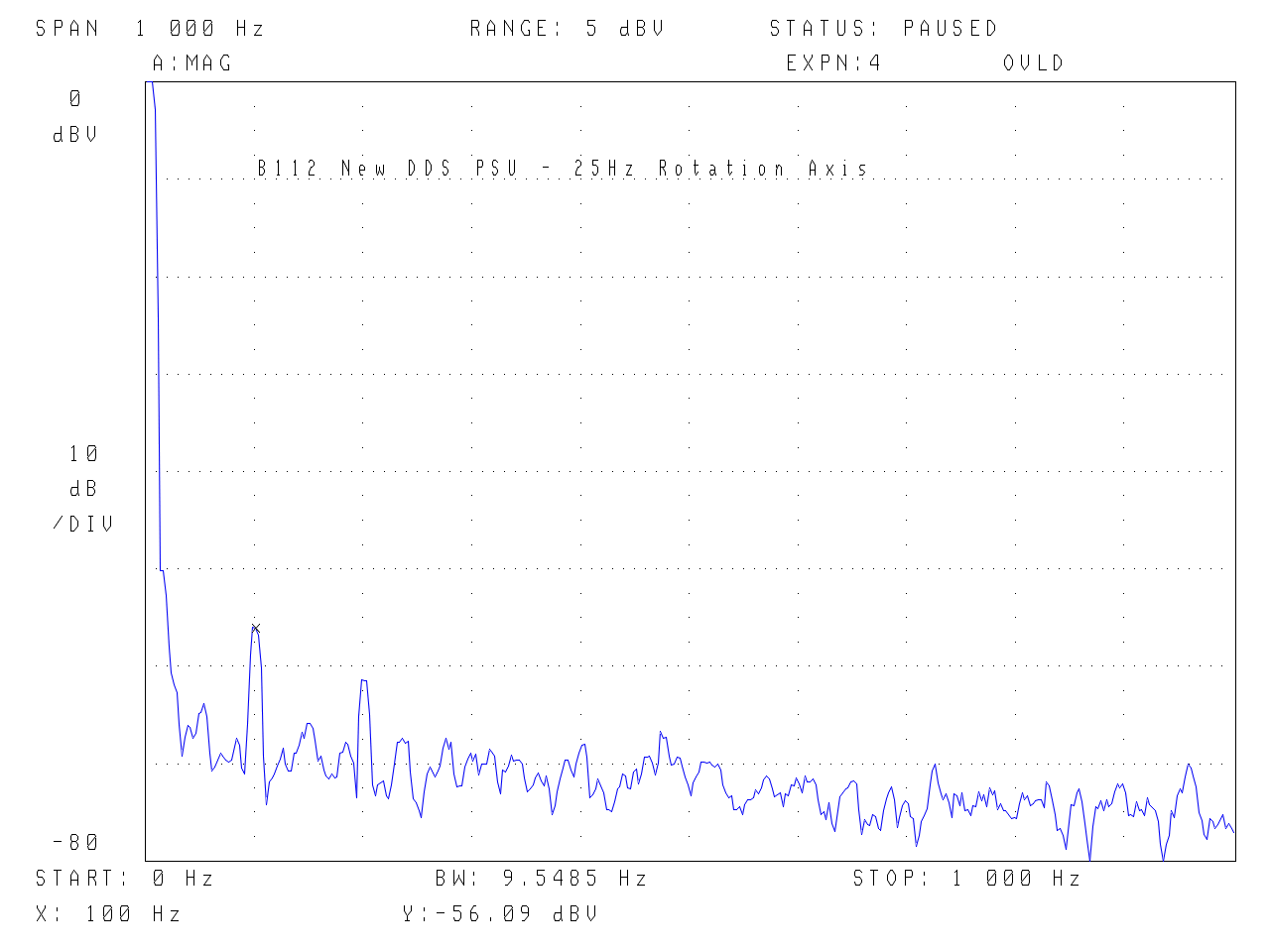
Moving on to vibration plots… There is a clear improvement over the original split phase PSU. Critical low frequency components at 25, 50, 100Hz are lower by 15dB or more, Even compared to the tuned phase PSU it is a further 10dB lower. This is a very good result. (noise floor is the same as all the other examples)
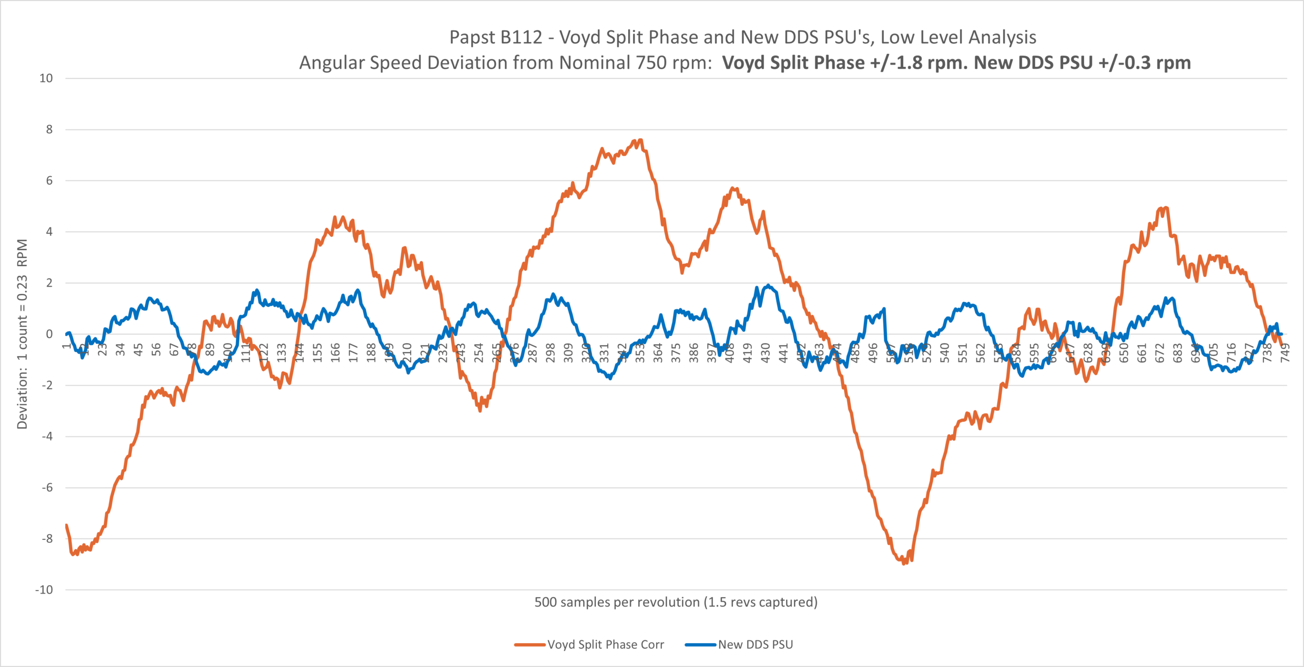
So, what does this mean – vibration as measured above is an indicator of rotational speed stability, but what is the actual rotational speed?
The New DDS PSU shows a small improvement over the previous best B112 drive (the old ‘tuned phase psu’) +/-0.4rpm is now +/-0.3rpm but a sixfold improvement over a carefully adjusted Voyd split phase PSU. If there was zero platter inertia then the best result would translate into a 0.04% variation (flutter) – on a 1khz tone this is 0.4Hz. For comparison, the MB12 etc. Linn motor has an 8.4% variation or 84Hz (if there was no platter inertia)! This further reinforces why with a light platter e.g. 1-2kg, the MB12 is a poor choice whether the standard one motor or even two. With two, the motor speed pulses will cancel in terms of side pull on the chassis but they will still attempt to cause flutter.